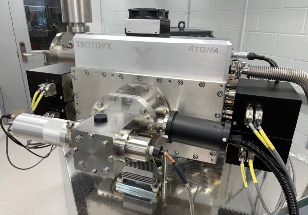
We get asked a lot of questions about our ATONA amplifiers, particularly relating to how they are used in the real world with real samples. So I’ll write on this blog from time to time in order to answer some of those questions. If you want to know more about ATONA you can also contact me directly, I’d be happy to hear from you (zenon.palacz@isotopx.com).
The recent development of ATONA amplifiers has demonstrated a remarkable reduction in Faraday noise when compared with conventional resistor technologies. The critical relationship is that the noise level of the circuit reduces directly proportionally to the integration time, rather than the square root of the integration time in a resistor. i.e for a 10 second integration the ATONA noise level is 2e-17amp and it is 2e-18amp for a 100 second integration. For a 1e13 ohm resistor it is (theoretical) 2e-17amp for a 10 second integration and 6e-18amp for a 100 second integration.
Thus for small ion signals, that last a long time, for example from a TIMS or plasma ion source then long integration times will result in the best signal/noise and hence precision for both ATONA and resistor, but the improvement in noise for the ATONA is three times better than a resistor.
An argument has been made that the benefit of the low noise of ATONA is removed when small integration times are considered, for example 1 second or less. In the case of the ATONA the 1 second noise is 2e-16A. Which is considerably lower than a conventional 1e11 ohm resistor but apparently not competitive when compared to the theoretical noise of a 1e13 ohm resistor ~6e-17amp.

What needs to be considered is why you need to integrate an ion signal for such short time intervals. There are only two real reasons. 1. The ion signal is short and transitory, for example in a laser ablated sample introduced into a plasma or 2. The ion signal is really large e.g. 1e-10 amp or above where the noise from the amplifier is a negligible source of error. This might occur in an aspirated sample in ICPMS, or from a large CO2 signal in stable isotope geochemistry, or a large transitory signal size produced in laser ablation ICPMS. Or total evaporation of a sample from a TIMS filament.
In the case of 2. the use of high ohmic resistors is impossible as they would saturate and not be responsive.
For transitory analyses an extremely rapid response to the ion signal (tau) is required. For example the rapidly changing ion signal is measured accurately and precisely without electronic artefacts being introduced into the measurement due to the slowness of the detector. For the ATONA the response is at the millisecond level and is not a detectable source of error. For a resistor the response is in seconds and is a major consideration in unstable ion signals for high ohmic resistors such as 1e13ohm. Requiring second order corrections to be applied to the data.
For very small transitory ion signals of tens or 100’s of cps then the only sensible way to measure these ion signals is by using an array of ion counting detectors. These detectors have noise levels at the count per minute level and hence the source of error is not the noise but the ion signal itself and of course the stability of the gain between the ion counting channels.
Ultimately the choice of detector and integration time is purely a function of the problem to be resolved. Having a detector with the minimum level of compromise or complexity is the ideal choice.
Thanks for reading! In my next blog post I’ll look at another aspect of ATONA amplification and how it relates to real sample measurement.
